This guide outlines essential steps for safely wiring solar panels, covering design, component selection, and installation best practices. It equips installers with clear instructions to achieve reliable, efficient, and code‑compliant solar systems. Follow these steps for safe, efficient solar power.
Safety First
Before any wiring, isolate power, verify voltage, and wear proper PPE. Use insulated tools, lock‑out tags, and double‑check connections. Follow local codes, keep a clean workspace, and maintain clear communication among crew to prevent accidents and ensure safe installation!!
Personal Protective Equipment (PPE)
When working with solar panels, wearing the correct personal protective equipment is essential to prevent injuries and ensure compliance with safety regulations. The core items include:
- Insulated gloves: Rated for at least 2,000 V to protect against contact with live wires.
- Safety glasses or face shield: Protect the eyes from debris, UV exposure, and arc flash.
- Electrical-rated footwear: Non‑conductive boots or shoes with rubber soles to reduce shock risk.
- Hard hat: Provides head protection near structures or when tools may fall.
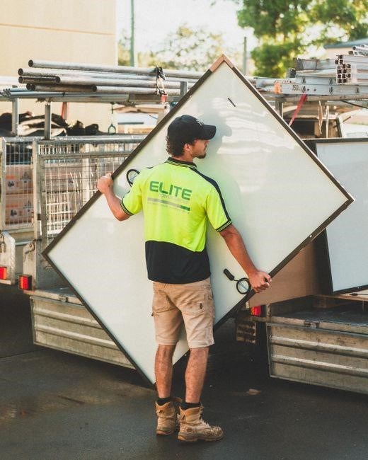
- High‑visibility clothing: Ensures visibility in busy sites and during maintenance.
- Arc‑flash clothing (optional): For installations where arc flash energy exceeds 1.2 J, use flame‑retardant garments rated for the expected flash boundary.
Additional precautions include:
- Verify all PPE is inspected before use and no cracks or wear are present.
- Use insulated tools rated 2,000 V, keep them dry and in good condition.
- Maintain a clean work area, free of conductive debris, to reduce accidental contact.
- Ensure personnel are trained in lock‑out/tag‑out procedures and understand installation hazards.
- Keep a first‑aid kit and fire extinguisher accessible in emergencies.
By adhering to these PPE guidelines, installers can reduce the risk of electrical shock, burns, and injuries, creating a safer environment for all involved in solar panel wiring.
Remember to document every connection, label all junction boxes, and perform a voltage test before energizing the system. Documentation ensures future maintenance is safe and efficient.
Site Inspection Checklist
- Confirm the mounting structure can support the panel weight and wind loads.
- Verify roof or ground mounting surface is free of cracks, corrosion, and debris.
- Check that the electrical panel and inverter are accessible and have sufficient clearance.
- Ensure proper grounding paths exist and are compliant with local codes.
- Inspect the area for potential short‑circuit hazards such as exposed wires or conductive surfaces.
- Confirm that the proposed wiring route avoids sharp edges, heat sources, and moisture ingress.
- Verify that the site has adequate ventilation for inverters and junction boxes.
- Check that the site has a reliable connection to the utility grid or battery bank.
- Confirm that all permits, inspections, and approvals are in place before work begins.
- Document the site conditions with photos and notes for future reference.
- Verify that all cable terminations are properly crimped or soldered with appropriate connectors.
- Check that all junction boxes are weatherproof and labeled with circuit information.
- Confirm that the inverter’s input voltage range matches the panel string output.
- Ensure that the system’s overcurrent protection devices are correctly sized for the wiring.
- Inspect for any signs of corrosion or damage on all exposed conductors.
- Confirm that the site has a documented maintenance plan and inspection schedule.
Planning the Wiring Layout
Plan the layout by mapping panel positions, routing paths, and connection points. Consider panel orientation, shading, and spacing. Determine cable routing to minimize length and voltage drop. Label all junctions and ensure clear documentation for future maintenance.
Understanding Panel Ratings
Solar panels are defined by a set of electrical specifications that dictate how they will perform in a system.The most critical values are the maximum power (Pmax), open‑circuit voltage (Voc), short‑circuit current (Isc), and the voltage at maximum power (Vmp). Pmax, expressed in watts, is the peak output under standard test conditions (STC) of 1000 W/m², 25 °C, and AM 1.5 spectrum. Voc is the highest voltage the panel can produce when no current flows, and it sets the upper limit for series connections. Isc is the current the panel delivers under short‑circuit conditions and informs the sizing of conductors and fuses. Vmp is the voltage at which the panel delivers its maximum power; it is the operating point for most string configurations. Temperature coefficients describe how the panel’s voltage and current change with temperature, usually given as a percentage per degree Celsius. A negative coefficient for Voc indicates a drop in voltage as temperature rises, while a positive coefficient for Isc means current increases. Understanding these ratings allows designers to calculate the optimal string length, select appropriate cable gauges, and ensure that the inverter’s input range is not exceeded. Additionally, the panel’s maximum power point tracking (MPPT) range, rated voltage, and current limits must align with the inverter’s capabilities. Proper interpretation of panel data sheets guarantees efficient energy harvest, protects equipment from over‑voltage or over‑current conditions, and ensures compliance with electrical codes and safety standards.
By mastering these ratings, installers can design robust, efficient, and safe solar arrays that meet performance expectations and regulatory requirements. This comprehensive understanding ensures that each string operates within safe voltage limits, that cable sizing prevents excessive voltage drop, and that the inverter’s MPPT range is utilized.
Determining String Configuration
Choosing the correct string layout is pivotal for maximizing system performance while maintaining safety and compliance. Start by evaluating the inverter’s input voltage window and maximum current rating. Match the panel’s Vmp and Isc to these limits, ensuring that the series‑connected panels do not exceed the inverter’s maximum voltage and that the parallel‑connected strings stay within the current capacity. Use the panel’s temperature coefficient to anticipate voltage shifts under hot conditions; this helps avoid exceeding the inverter’s upper voltage threshold. Next, calculate the expected voltage drop over the chosen cable run. Select a cable gauge that keeps the drop below the recommended percentage—typically 3–5% for most installations. Consider the physical layout: run cables along the shortest path, avoid sharp bends, and secure them to prevent mechanical stress. Incorporate junction boxes at points where the string splits or changes direction; these boxes should be rated for the panel’s voltage and current and provide a safe enclosure for splicing. Finally, document the string plan in a schematic, noting the number of panels per string, the total string voltage, and the current per string. This documentation aids troubleshooting, future expansions, and ensures that all components are correctly matched for efficient, reliable operation. The design should also account for future expansion, allowing additional panels to be added without exceeding the system’s limits.Efficiently
Selecting the Right Components
Choosing compatible parts is essential for safety and efficiency. Match panel ratings to inverter input limits, use proper cable sizes to reduce voltage drop, and select junction boxes rated for voltage and current. connectors and enclosures protect the system. Use components to compliance. and safety.
Inverter Compatibility
Selecting the correct inverter is critical for a solar system’s performance and safety. The inverter’s input voltage range must encompass the maximum voltage produced by the panel string, while its maximum current rating should exceed the panel’s peak current to avoid overload. Inverter efficiency curves also influence overall energy yield; higher efficiency at the operating point reduces losses. Additionally, the inverter’s power rating should match the total system capacity, allowing a safe margin for future expansion or temporary surges. Compatibility with the chosen panel’s power point (MPP) voltage ensures the inverter can track operating point.! Many modern inverters offer MPPT (Maximum Power Point Tracking) with multiple channels, enabling independent control of each string for better performance in partial shading. The inverter’s communication protocol (e.g., Modbus, CAN, or proprietary) must align with monitoring equipment to provide real‑time data and diagnostics. Finally, ensure the inverter’s environmental specifications—temperature range, humidity tolerance, and IP rating—are suitable for the installation site. Proper selection prevents voltage spikes, reduces wear on components, and guarantees the system operates within design limits, thereby extending lifespan and maintaining warranty compliance. When integrating the inverter, always verify that the cable gauge matches the current rating and that all connections are tightened to the specified torque to avoid heat buildup and ensure reliability!!
Junction Boxes and Connectors
Junction boxes serve as the central hub where multiple panel strings converge, providing a safe, enclosure for all connections. They must be rated for the system’s voltage and current, and have an IP rating that matches the installation environment. Selecting the correct box size is essential; oversized boxes create unnecessary bulk, while undersized ones risk overheating and fire hazards. The box should accommodate all conductors, fuses, and any future expansion, and feature a secure, lid to prevent accidental contact. Connectors are the interface between panels, cables, and the junction box. They must be corrosion‑resistant, typically made of stainless steel or aluminum, and rated for the maximum voltage and temperature of the system. The connector type—such as MC4, MC5, or proprietary—must match the panel’s output terminals. Proper crimping technique is vital; a loose connection can generate heat, reduce efficiency, and pose a fire risk. Use a calibrated crimping tool and verify each connection with a continuity test before sealing the box. Grounding is a critical safety feature; all metal parts of the junction box and connectors should be bonded to the system ground using a dedicated grounding conductor. This ensures fault currents are safely diverted to earth, protecting personnel and equipment. Finally, label each conductor clearly within the box, indicating polarity and string number, to simplify troubleshooting and future maintenance. Adhering to these practices guarantees a reliable, code‑compliant junction box and connector assembly that supports long‑term system performance.
Wiring Techniques
Use proper wire gauge, secure terminations, and maintain consistent polarity. Keep runs short to reduce voltage drop, route cables away from heat sources, and use conduit for protection. Follow local codes and manufacturer specs for optimal performance and safety. for safety.
String Wiring (Series vs Parallel)
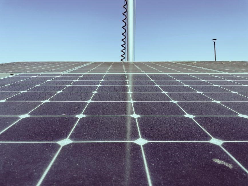
In solar arrays, the choice between series and parallel connections shapes voltage, current, and overall system resilience. Series wiring links panels end‑to‑end, adding each panel’s voltage while keeping current constant. This configuration raises the string voltage, allowing the use of fewer, higher‑rated cables and reducing copper costs, but it also amplifies the impact of a single panel’s failure, which drops the entire string’s output. Parallel wiring, by contrast, connects the positive terminals together and the negative terminals together, preserving the panel voltage while summing currents. This approach offers greater fault tolerance; a malfunctioning panel only affects its own string, leaving others operational. However, parallel strings demand thicker conductors to handle the higher aggregate current, and the voltage remains low, requiring more sophisticated inverter input handling. Engineers often blend series and parallel strategies: a “series‑parallel” string design balances voltage and current to match inverter limits while mitigating the cost of copper and the risk of cascading failures. Proper design also involves calculating the maximum series voltage (Vmax) and ensuring it stays below the inverter’s input threshold, as well as verifying that the total current does not exceed the cable’s ampacity. Additionally, the use of bypass diodes on panels helps maintain string performance when shading or partial shading occurs, especially in series configurations. When planning a string layout, consider panel orientation, expected shading patterns, and the desired fault tolerance. A well‑designed string configuration not only optimizes energy harvest but also simplifies maintenance and extends the lifespan of the entire solar installation.
When designing series‑parallel strings, the number of panels per string and the number of strings per inverter must be carefully balanced. A common practice is to keep the string voltage below the inverter’s maximum input voltage and the total current below the cable’s ampacity. This ensures that the system remains within safety margins while maximizing power output. The use of monitoring systems can also help detect under‑performance early, allowing for timely maintenance.
Cable Sizing and Voltage Drop
Choosing the right cable size is critical for both safety and efficiency in a solar array. The key factors are the expected current, the distance between panels and the inverter, and the acceptable voltage drop limit—typically 3% for DC systems. To calculate the required cross‑sectional area, use the formula: A = (I × L) / (S × Vd), where A is area in mm², I is current in amperes, L is one‑way length in meters, S is the conductivity of the material (≈ 56 S/m for copper), and Vd is the permissible voltage drop in volts. After determining the area, round up to the nearest standard cable size, such as 4 mm², 6 mm², or 10 mm². For long runs, consider using higher‑grade conductors like copper or aluminum with a lower resistivity, or install a DC optimizer to reduce the length of the main feeder. Additionally, the cable’s insulation type (XLPE, PVC, or RPE) affects temperature rating and, consequently, the ampacity. Always verify that the chosen cable can handle the maximum temperature rise under full load. Finally, use proper cable trays or conduit to protect the conductors from mechanical damage and to comply with local electrical codes. By adhering to these guidelines, installers can ensure that the solar system delivers optimal performance, complies with all regulatory standards, and remains safe for occupants and maintenance crews over its expected lifespan of 25 to 30 years. Furthermore, periodic inspections and replacement of components can prevent failures extend the array’s life.